CS 563 Advanced Topics in
Computer Graphics
The Wonderful World of Birds and Feathers
By:
Presentation Date:
This Paper is
based off of a presentation I gave on the some of the current techniques in computer
Graphics for modeling Realistic feathers and Birds. All pictures used in the paper are without
the consent from the authors of the papers my presentation was based on.
(Using
Bezier Curves)
(Using an L-System)
A lot of work has been done in the area of modeling nature. Some examples of this are the modeling of hair and fur on animals or the modeling of plants and water. Many different techniques have been discovered to create realistic plants and animals. This paper discussed a pair of techniques that are used to model realistic feathers and birds.
Both techniques can be used to model individual feathers. While the second is also able model the growing of feathers along a poly-mesh shape to create a bird. The first technique uses user specified Bezier curves to design and model the feather. The second technique uses an interactive interface to create the basic shape of the feather and an L-system to model the feather. This paper will discuss the general biological structure of a feather and the details of the two different techniques. The details of the two techniques will include the modeling, rendering, applications and future improvements.
 Structure:
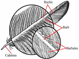
Both techniques discussed in this paper are based off the biological structure of a feather. This structure is shown in the picture to the right. The main parts that should be noticed are labeled in the picture. The base of the feather is called the Calamus which is the main stem of the feather (with no branching structures). The Rachis is the main stem portion of the feather where the branching structures start to the tip of the feather. The rachis is where the main body of the feather develops. The branching structures that extend from the rachis are called Barbs. The collection of barbs on either side of the feather’s body is known as Vanes. The number of barbs that originate from the rachis is a variable number. Each barb is built form sets of interconnected Barbules. The barbules help maintain the form of the feather. For some feathers the anterior and posterior barbules (which are interconnected to create the barb) are connected by microscopic hooks called Barbicles (not shown in the picture).
Types:
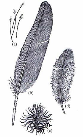
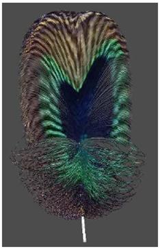
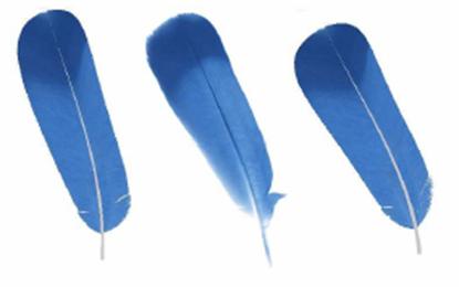
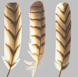
The modeling of a feather will depend on the type of feather that you want to model. The techniques that we will discuss take four main types of feathers into consideration. The picture to the right shows the four different types of feathers (hand drawn). Figure (a) is a Filoplume which is a small specialized feather. These are used mostly as decorative (an example would be a peacock). Figure (b) is the most commonly known feather, a Contour feather. The tight structure of the barbs in the contour feather is what allows birds to fly. The tight structure prevents air from passing through the feather and forcing it to go around it and be controlled. Figure (c) is a Plume which is the least structured feather. Plumes will be found under contour feathers and keep the bird warm. The last feather that is considered in the construction of these models is shown in figure (d) and is call the Semiplume. This is a combination of the contour feather and the plume feather so it also contains a combination of the benefits of both.
The first technique I discussed in my presentation uses Bezier curves to create a single feather. This technique is only set to model individual feathers. Each part of the feather is represented by a cubic Bezier curve. This allows for a lot of user control on the shape of the feather. Once all the curves have been user defined there are also parameters that are can be modified by the user. These parameters allow control over biological aspects of the feather which allow for the modeling of a more realistic looking feather.
Bezier Curves:
The first technique uses cubic Bezier curves to create the structure of a
feather. Here I only mention the use of
Bezier curves as I did in my presentation.
I have found a link that has a great explanation of Bezier curves. So if you need more details than what I talk
about here you can follow THIS
LINK (http://www.moshplant.com/direct-or/bezier/)
to get more information.
Each curve has four main points that
determine the shape of the curve. These
four points are the two endpoints and two control points. A Bezier curve is defined by two equations,
one for X and one for Y (as shown below).
A point on the Bezier curve line is defined by a time t that is set between 0 and 1. This time t is used in both equations to find the X and Y coordinates at
that time. Cubic Bezier curves allow for
a large number of possible variations of curves that can be 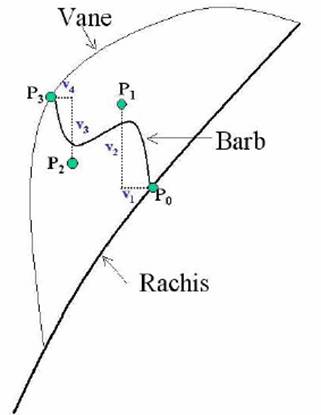 used in any feather modeled.
x(t) = axt3 + bxt2
+ cxt + x0
y(t) = ayt3 + byt2
+ cyt + y0
The modeling of a feather using Bezier curves starts with defining the general shape of the feather. A cubic Bezier curve is used to determine the Rachis. While a Bezier curve with five control points is used to determine each vane. Once these are determined the barbs are modeled.
The modeling of each barb is done separately though the outcome for each can be similar to those adjacent to it. The shape of the barb is determined by four control points as shown in picture. P0 and P3 are the endpoints located on the rachis and vane boundary respectively. P1 and P2 control the bend of the curve. The initial value of P1 and P2 are determined by the random variables (v1, v2) and (v3, v4) respectively. P0 and P1 are initially assumed to be the same point (as are P2 and P3). These random v values are used to modify their positions and can later be modified by specific parameters to change the position of the control points.
Parameters:
 Since the form of most feather isn’t
naturally consistent throughout an entire feather, specific parameters were
defined to allow control over the modeling of a feather. These parameters perform operations on the
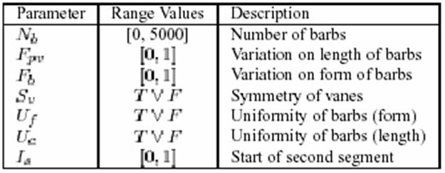
Bezier curves that create the basic structure of the feather. The parameters are listed in the chart to the
right. These parameters are each based
off of the biological study of the formation of a feather. These seven minimum parameters allow for the
real time generation of many different feathers, including all of the types
covered in the previous section. Below
is a listing of the meaning and the role each parameter plays:
Since the form of most feather isn’t
naturally consistent throughout an entire feather, specific parameters were
defined to allow control over the modeling of a feather. These parameters perform operations on the
Bezier curves that create the basic structure of the feather. The parameters are listed in the chart to the
right. These parameters are each based
off of the biological study of the formation of a feather. These seven minimum parameters allow for the
real time generation of many different feathers, including all of the types
covered in the previous section. Below
is a listing of the meaning and the role each parameter plays:
·
Number of
Barbs – Nb
This parameter controls the number of barbs that the feather will have in each vane
In testing they only used up to 2000 (max being 5000)
·
Variation
on length of barbs - Fpv
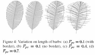
Each barb’s length can be randomly changed with this parameter. The value that it is set to lies between 0 and 1 (0 being no change and 1 being the largest change). In terms of the 4 points that are used determine each barb this parameter modifies the P3 point. The figure 4 (to the right) taken from [2] shows how this parameter can affect the look of a feather.
·
 Variation on form of barbs – Fb
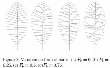
This parameter directly modifies the values of v1, v2, v3 and v4 based on a value give between 0 and 1. Since these values control the points P1 and P2 which control the curve of a barb, this parameter with modify the curve of each barb.
This parameter scales the distance between P0 and P3. Figure 5 (to the right) taken from [2] shows how this parameter can affect the look of the barbs given that the initial random configuration is that each barb is a straight line from P0 to P3.
·
Symmetry
of vanes – Sv
This is a Boolean parameter which
controls whether or not the two vanes are symmetrical. If the value is TRUE then the form and length
of the barbs in both vanes will be identical.
If the value of Sv
is FALSE then different values will be generated for the Fpv and Fb
parameters and the barbs on one side will differ from the barbs on the other.
·
Uniformity
of Barbs (shape) – Uf
Some types of feathers have a regular shape like the contour feather. The shapes of the barbs are almost identical in these types of feathers. This parameter allows for control over the uniformity of the shape of the barbs. If Uf is set to true the values used to determine the shape of the initial barb (the Bezier curve that is generated with four random v values) will be used to determine the shape for the rest of the barbs. When the value is FALSE then there is no uniformity among the barbs.
·
Uniformity
of Barbs (length) – Uc
This parameter is used to maintain the uniformity of the length of the barbs. Again this is a Boolean parameter. If it is set to TRUE then they do not pick a different Fpv each time. If it is FALSE then they do select a different Fpv each time.
·
Start of
second Segment - Is
This is another value that is done by a percentage from 0 to 1. This parameter determines if a second segment will be implemented on the feather being modeled. As you have seen from some examples, there are feathers that are uniform for a part and not for the other part (such as a semiplume). In such feather this parameter allows us to divide the feather into two pieces (top and bottom) and determine different parameters for both. The value chosen between 0 and 1 determines where on the rachis the division occurs.
Rendering:
 With
the feather model complete we can render it in two ways photorealistic
and non-photorealistic.
With
the feather model complete we can render it in two ways photorealistic
and non-photorealistic.
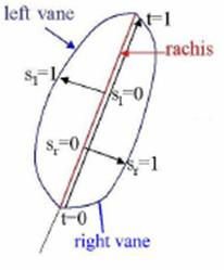
Photorealistic rendering uses a texture map which can be
either images of a real feather or painted images. When rendering the individual barbs the
texture map is referenced using (s, t) coordinates. The s represents a value from 0 at the rachis
to 1 along outer edge of the feather while t represents a value of 0 to 1 along
the rachis (0 being the base and 1 at the tip) (the picture to the right may
help shows this). The texture map is
divided into two parts, one for each vane.
Some colorful examples of photorealistic rendering are shown below.
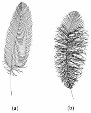
Non-Photorealistic rendering done without a texture map, when
the feather is rendered in this way it looks like a hand drawing. The rendering for this is faster but it
doesn’t look as pretty. On the left of
the photorealistic rendering of peacock feather are two examples ((a) and (b))
of the non-photorealistic rendering.
Samples:
The second technique I discussed in
my presentation uses an L-system to create the model of a feather. The rendering of the feather is done with a
bidirectional texture function (BTF). The
use of an L-system in this technique allows for the modeling of both an
individual feather and the growing of feathers on a bird. Here I will discuss the use of this technique
in the modeling and rendering of both types.
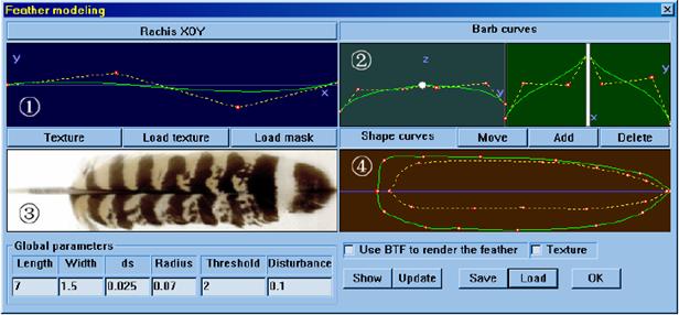
Shape interface control:
First we will take into
consideration the modeling of an individual feather. To create this model we need to first define
the shape of the feather. To create the
initial feather shape a user interface was designed that gave a lot of control
to the user. A screen shot of this
interface is shown below. The first
window in the interface allows control over the curve of the rachis (or main
stem) of the feather. The second window controls the barb curves for the right
and left vanes. The third window is a
texture supplied by the user. While the
forth window defines the left and right outline curves (shape of the
vanes).
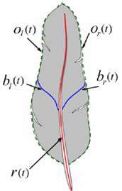
The user defined curves are
represented as functions. The rachis is
represented as r(t), the barbs are represented as bl(t)
and br(t) (depending on whether the barb is on the left or right),
and the outline (shape of the vanes) is represented as ol(t) and or(t)
depending on whether is it the left or right outline of the feather. These functions are displayed in the diagram
to the right. Not all feathers are
symmetrical so the large amount of control over the shape of the outlines for
the feather allows for a more realistic modeling.
L-System Model:
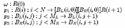
The modeling of an individual feather is done with an L-system. An L-system presents the development of a branching structure through a production. The structure of a feather can be broken up into repeated units called modules which we can use to develop our L-system. Below is an example of a basic L-system to create an individual feather.
Here are some
definitions for the variables that have not already been given:
· N – length of feather and density of Barbs
· ML and MR – Define lengths of left and right Barbs
· R(0) generates feather based on rachis and barb curves
· p1 generates first segment of rachis and two barbs
· p2 generates left barb segment
· p3 generates right barb segment
 This
L-system will generate a feather (axiom R(0)) based on
the rachis and the barb curves.
Production p1 will
create the first segment of the rachis curve r(t) and
generate a barb on each side of the rachis using recursion. Productions p2 and p3
will generate a segment according to the left and right barb curves
respectively. An example of the type of
feather that this system will produce is shown in the picture to the right, on
the left most side of the picture.
This
L-system will generate a feather (axiom R(0)) based on
the rachis and the barb curves.
Production p1 will
create the first segment of the rachis curve r(t) and
generate a barb on each side of the rachis using recursion. Productions p2 and p3
will generate a segment according to the left and right barb curves
respectively. An example of the type of
feather that this system will produce is shown in the picture to the right, on
the left most side of the picture.
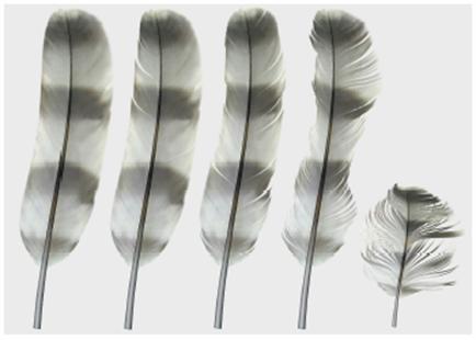
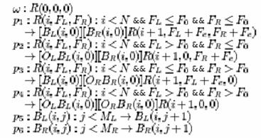
As you may be able to see this feather doesn’t look that real. The barbs in it are too perfect. The barbs of a feather are held together by little hooks call cilium. These hooks are instrumental to a bird’s ability to fly. Birds often have things that brush their feather and will create spaces between barbs, thus detaching the hooks holding them together. An example of this would be if a twig were to brush the feather and part the barbs. The L-system was modified to take this affect into account. To do this a threshold for the cilium was introduced F0. Also the force exerted on the left and right barbs is represented by Fl and Fr. This changes the production of p1 to p4 by adding that for each step that we move along the rachis we increment Fl and Fr by and a random external force Fe. If the force of Fl or Fr exceeds that of F0 exerted by the cilium then the barb is rotated by some random degree in the direction determined by the barb. The new L-system is shown below. The results of this L-system are shown in the four rightmost feathers shown in the picture to the right (or above as the case may be).
BTF – Bidirectional
Texture Function:
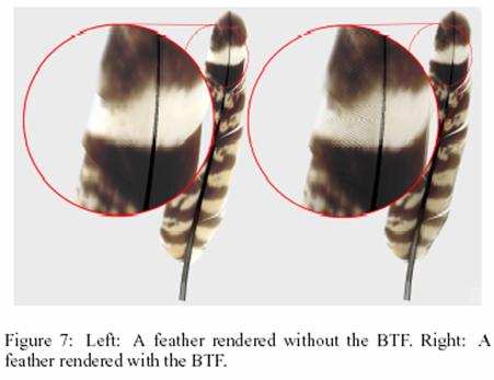
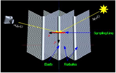
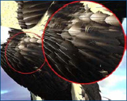
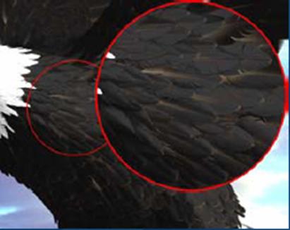
A BTF is used to capture the mesostructure and the directional radiance distribution at each point on the feathers surface. The BTF that they used is only a five dimensional function though because they only sample it along the X-axis. The other dimensions are viewing directions v coordinates (θv, φv), and the lighting direction l (θl, φl) at surface point (x, y) (of course only the y matters since the x is dropped). To calculate the BTF the geometry of the barbs is built as shown in the figure below. This structure is rendered with all viewing and lighting settings. The rendering is done offline so a complex structure is affordable. They found the 5D rendering using the BTF to suffice for rendering an actual 6D BTF. This model is opaque with both diffuse and specular reflections. Also the BTF allows for the capturing of oil film and iridescence with is common among many birds. This technique for rendering allows for a large amount of detail to be seen close up. This is shown in the figure of hawk feathers below.
An Entire Bird:
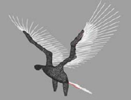
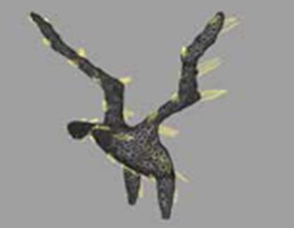
The last portion of this technique allows for the growth of feathers along the entire body of a modeled bird mesh. Their system allows for a user to place some key feathers along a polymesh of a bird and have the rest interpolated. The initial step is to create the skeleton of the wings and tail as shown here. This skeletal structure is based on the biological set up of the wings and tails. There are certain types of feathers and orderings that these feathers are put in so they look realistic. The user will specify 8 key feathers on the wings and 4 on the tail, the system will interpolate the rest.
The next step for the system is to create the contour feathers. These are the feathers that cover the body of a bird. The large number of feather and their different sizes that are included on the body of a bird makes it impossible for a user to specify all of them. This system allows the user to specify specific key feathers and their growing direction on the body of the bird and allow the rest to be interpolated. The picture below shows the specification of specific feathers and their growing direction by the user. Once these specific feathers have been determined the rest can be interpolated as shown in the figure to the lower right.
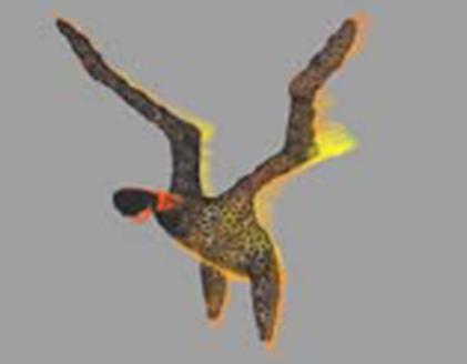
When render the feathers of a bird using just the given mesh they found that because a feather was rendered at each vertex on mesh spaces occurred throughout the body of the bird. This would obviously not look realistic so to solve this problem they implemented Turks Algorithm which basically sub divides a polygon into smaller sections. This process is actually the first step in this process even though I am talking about it after have explained some of the other steps. Now the process is able to render feathers for each vertex, each with their own growing direction and size. Below is an example of such a rendering. As you can see this rendering looks far from real. The problem that occurs is that there is collision among adjacent feathers forcing an unrealistic look. They solved this problem by creating a collision detection algorithm. The process of this algorithm is shown to the right. The algorithm will rotate the feather toward the surface normal until no collision is detected. Then the algorithm moves to the adjacent feathers and recursively solve for their growing direction. Below is an example of the rendering after the collision detection has been run. Even farther down is an example of a final rendering.
Conclusion:
Here I have discussed two different
techniques for modeling feathers. The
first used Bezier curves to create an individual feather and the second used
L-systems to produce both individual feathers and the growing of feathers on a
bird. Both produce very realistic
results. Even though the first technique
produces an accurate rendering of a feather it does not have the level of
detail that the second does. The use of
L-systems in the second technique allow for a large amount of detail and a more
realistic rendering. Also the first only
take into account an individual feather.
The ability to model the entire body of a bird with feathers makes the
second technique much more useful. Both
techniques have a lot of area that they can consider to extend there uses. The L-system technique produces a beautiful
bird but the bird is too perfect. More
work can be done to model the look of the bird to allow it to appear more
realistic. The Bezier curve technique
could work to implement to use of rendering an individual feather into the
rendering of feathers on an entire bird as was done in the L-systems technique.
[1] Chen Y et al, "Modeling and rendering of realistic feathers ", Proc. ACM SIGGRAPH 2002
[2] Franco C.G. and Walter M., "Modeling and Rendering of Individual Feathers", Proc. SIBGRAPI 2002
[3] Franco C.G. and Walter M., "Modeling the Structure of Feathers", Proc. SIBGRAPI 2001
[4] http://www.moshplant.com/direct-or/bezier/
[5] http://www.geocities.com/cocoo_chen/