
|

CS 563 Advanced Topics in Computer Graphics: Introduction To Image Based Rendering
Cliff Lindsay - Spring, 2003 WPI
1. Introduction
Up to this point, we have focused on showing 3D objects in the form of polygons. This is not the only approach to get an object to the screen, nor is it always the most appropriate. It is not uncommon for computer graphics experts to begin presentations and published works with such a statement, "The ultimate aim of realistic graphics is the creation of images that provoke the same responses that a viewer would have to a real scene." This is essentially true regardless of how an object's image is displayed on a screen, as long as it is realistic. Image Based Rendering combines two disciplines, Computer Graphics and Computer Vision, to apply the best of both techniques for rendering realistic images.. This paper is going to describe several techniques for rendering realistic images using non-classical rendering approaches.
Figure 1. Computer Vision[cohen99].
First, simple 2D techniques for displaying convincingly real images for several complex objects will be discussed. Then, 3D approaches that generate novel views from real or synthetic images will be examined. Lastly, 4D approaches for rendering images will be presented along with future directions for geometry-less graphics that may change the way we think about Computer Graphics primitives. Figure 2 compares the several different techniques for rendering graphic scenes. This will show a progression of rendering techniques that will increasingly decouple itself from geometry.
Figure 2. Rendering Spectrum[Akenine-Moller02]
2. 2D Image Based Rendering
The origins of Image Based Rendering (IBR) stem from the consequences associated with More's Law, which states computational power doubles every 18 months. While computer-processing power increases at tremendous rates, our ability to develop complex and diverse models lags considerably behind computational capabilities. Therefore, the need for more complex models has resulted in the development of alternative approaches such as IBR.
As the need for better models to place in our virtual scenes has grown, so has our ability to capture image-based models. There is a plethora of inexpensive image acquisition hardware on the market these days such as digital cameras, scanners, and digital video devices. Also, recent trends in graphics display hardware have made it very easy to incorporate image based rendering into general rendering applications (e.g., CAD). In addition graphics hardware companies have been using IBR techniques for some time now in the form texture acceleration, which is a simple example of IBR.
Texture mapping is the process by which a source image (texture) is mapped onto a surface in 3-D object space, which is then mapped to the destination image (screen) by the viewing projection. Texture space is labeled (u, v), object space is labeled (xo, yo, zo), and screen space is labeled (x, y). However, because the source and destination images are both 2-D in nature, the process by which the source image is mapped onto a 3-D object space is often bypassed. . Overlaying an image across the surface of an object increases the apparent complexity of the object without causing significant rendering overhead.
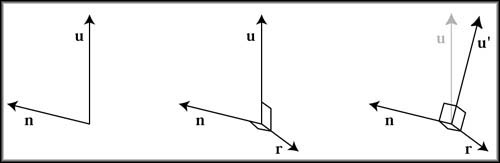
Figure 3. Bilboard Transform[Akenine-Moller02]
There are other simple 2D techniques for displaying images on a screen such as Sprites, Billboards, Impostors, and Image Layering. Sprites, Billboards, and Impostors employ an off screen technique to render the image, then apply that image as a texture to some bounding geometry. The texture is applied to the center of a bounding polygon, then the polygon's normal is oriented directly toward the viewer giving the appearance of complex geometry. However, if the texture resolution exceeds screen resolution, there is a possibility that texels (texture pixels) will be visible and reveal the illusion.
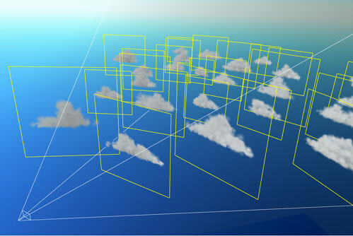
Figure 4. Bilboard Example[Akenine-Moller02]

Figure 5. Rendered Bilboard Example[Akenine-Moller02]
Image Layering employs a technique similar to traditional animators' cell layering. This technique involves layering images at different depths in order for the images to be prioritized according to depth. Images closer in depth will receive more resources for rendering than images at a farther depth. This is, essentially, a priority-rendering scheme with impostors. This approach, while simple, is very effective and has been implemented extensively in game programming.
Splat kernels are also employed in 2D Image Based Rendering with extensive use of texture hardware to apply contribution of images to pixels. Splats are basically the projection of a volume onto the screen by "throwing" and spreading the energy distribution of volume elements onto the image plane. A Splat kernel is a specific algorithm used for distribution (shape of splattering using alpha values) of the parts (Gaussian-Cload, Bilinear-Patch, etc.).
3. 3D Image Based Rendering
3D IBR involves the addition of several techniques that adds to the realism of rendered images but with only slightly increased complexity when compared to 2-D approaches. Examples of 3D IBR include Layered Depth Images, View Morphing, and View Interpolation.
View interpolation is a linear interpolation of pixels from one location to the other using Morph maps. For view changes of small degrees, this technique closely approximates images obtained with a camera within small angles but losses this trait with larger camera angle changes. There is a significant amount of error for large angle view changes because the warping function is not based on a real camera system. Also, the choice of interpolation functions can considerably impact the warped image. For example, the use of a cubic or quadratic interpolation can improve the results at the expense of higher computation rates. Also, holes can arise when an occluded image is currently in view. Lastly, view interpolation is limited to linear or non-panning view changes because the camera moves along a line and does not for panning around the object.
View morphing, on the other hand, allows for greater camera angle changes and is more flexible on the path the camera can take (e.g., parallel views). In addition, view Morphing has an additional Prewarping step to the process prior to the Interpolation step. Prewarping brings the image planes into alignment without changing the optical centers of the camera [seitz96]. As a result, regardless of the projection of the key images (i.e., source and destination), Viewmorphing will be able to smoothly interpolate between the two images. In addition to a Prewarping phase, there is also a Postwarp phase that ultimately yields the image. The Prewarping and Postwarping, along with the intermediate interpolation, require multiple image resampling operations that can make the image blurry in between key images. Certain measures are taken to reduce this artifact (see the paper for more details [seitz96].
Figure 6. View Morphing Visual Description[chen95], image from[watt00].
4. 4D Image Based Rendering
The final IBR approach implements a 4 dimensional function for rendering, a simplified Plenoptic viewing function. Two methods for rendering camera views for synthetic and real world scenes from image data have been recently developed. These techniques are called The Lumigraph and Light Field Rendering. Both of these techniques have their roots in the 5D Plenoptic function which can be reduced to 4D assuming no occlusions for the scene (completely inside or completely outside).

Figure 7. plenoptic Function[Mcmillian95].
The Lumigraph model uses a reorientation of the parameters to create the 4D function. This model takes the rendering image and bounds it with a cube. This simplifies the function by allowing the restriction of the restriction of the Plenoptic function to a bounding surface. With the Lumigraph, plugging in appropriate values for two planes generates a view from a given point in a particular direction. With each face of a cube consisting of two planes, a ray is cast to the first plane, while the second plane is used to gauge the parameterization of the ray with the two-plane intersection. This parameterization technique results in a very efficient model for rendering a scene. A series of sheared perspective projections is stored in the outer plane and the inner plane then specifies a frustum bound bundle of rays. This bundle is responsible for coloring the image plane for that view, where the colors are ultimately sampled.
Figure 8. Cubed Extents Of Image, Each point on a cube has
multiple rays emanating[Gortler96].
The result of the plane - ray intersections provides discreet values that can be used to efficiently simulate light transfer in the scene. These discreet values on the grid are RGB values. The RGB values for both grids (i, j, p, q) are multiplied by the basis function and then summed to get the proper radiance. Before the radiance values can be determined, the RGB values must be projected into the space of the basis function used in the sum. Examples of basis functions include a 4d box, L2 distance metric, along with many other basis functions. The projection is defined as the integration of the duals of the basis function [Gortler96].
Figure 9. Parametrized Ray Plane Intersection[Gortler96].
Figure 10. Parametrized Ray Plane Intersection can converted to 2D[Gortler96].
Light field rendering and The Lumigraph consist of similar techniques. For example, they both use two planes for representation (A.K.A. light slab) and multiple light slabs. Therefore, familiarity with one model will aid in the learning of the second approach. These methods tend to have very large data set and more research is needed for compression for these sets. The big performance gain with these approaches is in the geometric calculations needed to represent a new view. Given a basis function continuous luminance is just a linear sum and can be looked up via the i, j, p, q values of the grid.
Figure 11. Continuous luminance is a linear sum [Gortler96].
Here is an example of a rendering from the Lumigraph paper.
Figure 12. Lumigraph Example [Gortler96].
5. Conclusions and Future Direction
In conclusion, Image Based Rendering demonstrates significant advantages in comparison to its geometric counterpart (i.e., classical rendering). An important advantage is the computational efficiency to photo realistic ratio. Image based rendering provides constant time rendering when there is a vast amount of frame coherency, and usually linear time when it is not coherent. That alone would be sufficient to invest in IBR, but there many more advantages such as decoupling rendering and scene complexity, pre-computation of scenes and images, as well as a more natural input space for the scenes (images as opposed to geometry).
However, there are also disadvantages to implementing IBR such as size and storage of data. But, given that the advantages far out way the disadvantages, IBR could be the wave of the future with respect to "classical rendering", and future research will continue to explore these exciting new approaches to rendering images.
A couple of recent advancements in the field of Image Based Rendering:
- Surface Light Fields Walter et al and Miller et al have used these to store pre-computed global illumination solutions.
- Radiance Maps are useful for representing true illumination values in image-based rendering applications, and are useful for recording incident illumination and using this light to illuminate CG objects for realistic composition
- VDTM is a technique for generating novel views of a scene with approximately known geometry making maximal use of a sparse set of original views.
- Image-Based Objects (IBO) An alternative object representation for computer graphics. In this approach, objects are represented by images that are then used to render arbitrary views of the objects with correct perspective. Image-based object can be constructed from either synthetic models or real objects, and can be translated, rotated, scaled and used as primitives to construct more complex scenes. We also present a painter's style algorithm for rendering such scenes.
References:
- Mcmillian, Leonard, Bishop, Gary, "Plenoptic Modeling: An Image-Based Rendering System", Proceedings of SIGGRAPH 95
- McMillan, Leonard, Gortler, Steven, "Applications of Computer Vision to Computer Graphics", ACM Siggraph,
- Chen, S.E., Williams L., "View Interpolation for Image Synthesis", ACM Siggraph '95
- Gortler, S, Cohen, M, Girzesczuk, R, Szeliski, R, "The Lumigraph", ACM Siggraph, 1996
- Seitz, Steven, Dyer, Charles, "View Morphing", ACM Siggraph 1996
- Watt, Alan, 3D Computer Graphics, Addison-Wesley Pub Co, 3nd edition, 2000
- Akenine-Moller, Tomas, Haines, Eric, Real-Time Rendering, 2nd Edition, A K Peters, 2002
- Cohen, Michael, "Course on Image-based, Modeling, Rendering, and Lighting", Siggraph 99
|