CS 563
Advanced Topics in
Computer Graphics
Image-based Techniques and Indirect Methods
by Guy Mann
Image based lighting is a technique
used to give 3d objects realistic reflections to make them appear to be within
a stored image. IBL works by capturing real-world illumination as an omnidirectional,
high dynamic range image and mapping the illumination onto a representation of
the environment. A 3D object is placed
inside the environment simulating the light from the environment illuminating
the computer graphics object
To perform IBL the graphics engine must map a Light
Probe Image to a large sphere surrounding the model. When a ray 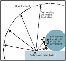 hits
the IBL environment it takes on the pixel value of the corresponding point in
the light probe image. Thus when the raytracing is performed any rays which travel from the
camera to the object then reflect onto the environment sphere will cause the
object to show a reflection of the point where the ray hit environment on the
objects surface. This gives the object the
appearance of being in the scene.
hits
the IBL environment it takes on the pixel value of the corresponding point in
the light probe image. Thus when the raytracing is performed any rays which travel from the
camera to the object then reflect onto the environment sphere will cause the
object to show a reflection of the point where the ray hit environment on the
objects surface. This gives the object the
appearance of being in the scene.
It is necessary, in order to map the image to a sphere, to use a
specific type of image called a light probe.
Light probe images capture all the light in a 360 degree rotation and
represent this light in such a way as to make the mapping of the light probe
onto the sphere simple. Light probe images are usually created from
multiple images to give an exacting account for all the light in the
scene. It is possible to use a single
image as a light probe.  To do this a
single high dynamic range image is taken of a mirrored
ball. The ease of this method has the
drawback that the image will show the camera and the photographer and that the
light is not well sampled in the area that is opposite the camera.
The other assertion about the image other than it being a light probe was that it had high dynamic range. The
“dynamic range”
of a scene is the contrast ratio between the brightest and darkest part. A high dynamic range or HDR image has a
greater dynamic range than shown on a standard device. In this type of image the pixel values are  proportional to
the amount of light in the world corresponding to the pixel. To create an HDR image typically multiple
normal images of the same scene with different light intensities are combined.
proportional to
the amount of light in the world corresponding to the pixel. To create an HDR image typically multiple
normal images of the same scene with different light intensities are combined.
IBL can also be used to give a real set of objects the appearance of being part of a scene just as before we used it to place rendered object in a scene. This is done by taking a large set of images of the object as illuminated by all possible directions. The linear combination of the images can produce images under arbitrary lighting conditions. The IBL environment determines the combination of the images by defining the location and color of incoming light and thus constraining the linear combination of the photos of the objects being lit.
It is possible to measure the
physical BRDF of a material without a gonioreflectometer using image based BRDF measurement. This technique uses fewer
measurements to define the BRDF than a gonioreflectometer and is less expensive
to setup. However the draw back is that
it is only possible to perform measurements on surfaces which can be placed on
the geometry of a physical sphere, such as coatings 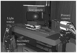 or sheets of flexible material. The physical
setup involves a fixed position primary
camera, a light source, a secondary camera for position measurement, a sample,
and photometric targets on the sample container. The sample is a sphere which can be painted
with a coating or a flexible sheet wrapped into a cylinder around the sphere.
or sheets of flexible material. The physical
setup involves a fixed position primary
camera, a light source, a secondary camera for position measurement, a sample,
and photometric targets on the sample container. The sample is a sphere which can be painted
with a coating or a flexible sheet wrapped into a cylinder around the sphere.
The mechanism for measurement works by
photographing the sphere from a fixed position and illuminating the sample from
a sequence of known positions. The light
sources position is variable so the exact 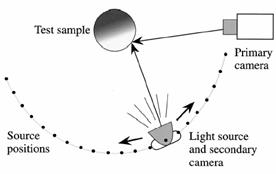 position of the light source is measured using a
secondary camera. The image is capture
by setting up and determining the fixed position of your primary camera. The secondary
camera is aimed at the sample and mounted below the light source to image the
photometric targets. The shutter on the
primary camera is opened. The opening of
the shutter on the secondary camera triggers the flash which provides the light
for the picture. This acquires the light
location measurement and the measurement image at exactly the same time.
position of the light source is measured using a
secondary camera. The image is capture
by setting up and determining the fixed position of your primary camera. The secondary
camera is aimed at the sample and mounted below the light source to image the
photometric targets. The shutter on the
primary camera is opened. The opening of
the shutter on the secondary camera triggers the flash which provides the light
for the picture. This acquires the light
location measurement and the measurement image at exactly the same time.
To
extract the BRDF from this type of setup 32 measurement images were taken from the primary camera or 96 when three
filters are used for RGB. Also 32 light
source calibration images from the second camera were used for finding the
light position for each measurement image.
Using the targets visible in the calibration images to establish the poses
of the secondary camera the light source position is computed. The samples position is found by taking the
image of the test sample in one of the photographs from the primary camera and
using its size and position to determine the sample’s position. Finally to determine the BRDF the images are
sampled using the known geometry to obtain measurements which will define the
surface’s BRDF.
The
photometric targets which are used to determine the light position are mounted on the base on the
sample. The targets have a known 3D
position relative to the sample and the primary camera ![]() and so by analyzing the light
location measurement image the position of the secondary camera and thus the
light source can be determined. This
method is accurate to a few millimeters. The sampling
of the images to extract the BRDF is done by processing each image
individually. First the surface point
and the normal of the sphere is determined for each pixel. The
direction of illumination is computed relative to the surface point and the normal and the
relative irradiance is computed from the known source geometry. Then by dividing the radiance from the pixel
value by the computed irradiance we can find the BRDF.
and so by analyzing the light
location measurement image the position of the secondary camera and thus the
light source can be determined. This
method is accurate to a few millimeters. The sampling
of the images to extract the BRDF is done by processing each image
individually. First the surface point
and the normal of the sphere is determined for each pixel. The
direction of illumination is computed relative to the surface point and the normal and the
relative irradiance is computed from the known source geometry. Then by dividing the radiance from the pixel
value by the computed irradiance we can find the BRDF.
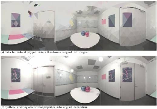
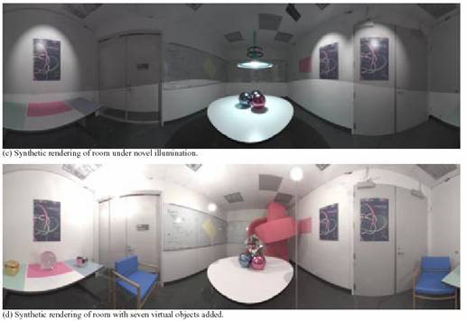
The goal of inverse global illumination is to model a real world scene with a realistic reflectance properties, from images of the scene, which can be given novel lighting conditions or have 3D objects placed in it. The technique works by
estimating the incident radiances of the surfaces in a scene. With the radiance estimates the reflectance properties of the surfaces in the scene are estimated by an iterative procedure. Reflectance property estimates can then be used re-estimate the incident radiances. The
input to the algorithm is: the geometric model of the scene, a set of radiance maps taken under known direct illumination, a partitioning of the scene into areas of similar non-diffuse reflectance properties used to estimate the reflectance properties of the surfaces in the scene by an iterative procedure. This means that to perform inverse global illumination we need a full geometric model of the scene as well as a set of photos of every surface with a spectral highlight on it and photographs of the whole scene. Inverse global illumination is based on inverse radiosity. With inverse radiosity we can determine the diffuse portion of the reflections within the scene. Inverse radiosity works by
Breaking
the surfaces in the environment into a finite number of patches. Each patch is assumed to have constant radiosity and diffuse albedo. For each patch:
Bi and Ei are
measured from a photo with known geometry. Fij is
derived from the geometry. So we can
find the diffuse portion of the reflection: ρi = (Bi - Ei)/(ΣjBjFij). Once we can determine the diffuse portion of
the reflection for the surfaces we are left to find a method of defining the
spectral reflections.
To find the spectral term we will first talk about a method for determining the spectral reflection of a surface when it is directly illuminated. Once we have this information we can use the spectral information to understand the case of mutual illumination with both spectral and diffuse reflections. To recover the specular parameters the radiance image must cover an area with a specular highlight or we will not have enough information. To find the BRDF of the surfaces in the scene with both spectral and diffuse reflection taken into account we use the following equations.
Li = (ρd/π + ρsK(α,Θi))Ii
Li is the radiance;
Ii is the irradiance;
ρd/π is the diffuse term
ρsK(α,Θi) is the specular term
α is the parameterized surface roughness
Θi is the azimuth of the incident and viewing directions
From the data from the images collected we can solve the nonlinear optimization problem and get parameters for ρs, ρd and α. With these diffuse and spectral terms we can then go about determining the mutual illumination because we can determine how the light bounces off all the surfaces in the scene.
To find the
BRDF of the surfaces in the mutual illumination case we use
the methods for finding the illumination of the surfaces in the direct
illumination case, the on above. We use
the direct illumination case as the initial estimates of the BRDFs of the surfaces.
From the initial conditions we iterate through the surfaces
recalculating the BRDFs for the surfaces based on the
amount of illumination the surface acquires from the reflections off other
surfaces.
References
1.Debevec P., “Image-Based Lighting”, IEEE Computer Graphics
and Applications March/April 2002, pp. 26-34
2.Yu, Debevec, Malik,
Hawkins, "Inverse Global Illumination: Recovering Reflectance Models of
Real Scenes from Photographs", Proc. ACM SIGGRAPH 1999
3.Marschner S.R., Westin S.H., Lafortune
P.F., and